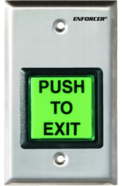
Today, businesses often implement security measures to prevent unauthorized personnel from getting into a building or restricted area. To do this, access control systems are installed on doors, exits, and gates. This ensures that only authorized individuals are granted access to the building. At the same time, someone inside the building will want to exit. However, exiting the building does not require any sophisticated equipment. Only a simple device will be needed to unlock the door. The push to exit button is often the item of choice.
Push to exit buttons are an essential part of access control applications. While access control systems like Kisi are great for securing your spaces, ensuring only authorized individuals can enter, there is often no need for credentials when exiting into a less secure place. This request to exit (REx) device allows you to open a locked door to exit without needing credentials.
It is a spring-loaded button, often mounted on a stainless steel plate. The button comes in different styles. It can be a simple or large button, green, or a button with LED lights. Push to exit buttons and motion sensors are the two most common REx devices.
Watch the video below for more information on push to exit buttons, their benefits, use cases, and installation tips.
One of the advantages of the push to exit buttons is their versatility. Exit buttons are suitable for use in electronic locking solutions, which need to provide a free exit option on the door. You can use the push to exit button on fire doors, gates, or anywhere you can install an access control system. It can be used as exit devices in residential, commercial, and industrial buildings.
In some cases, the push to exit button can be used when the access control panel fails to unlock the door. It can be used when the door’s handle isn’t suitable, or the user is unable use it. The button must be able to hold enough power for the door to open freely.
The push to exit button is wired to the access control system that controls the door's locking mechanism. Anyone that needs to exit the building or pass through the door can simply push the button.
When pushed, it momentarily releases the fail-secure or fail-safe lock of the door. The exit button releases power to the magnetic lock. With this, the door automatically releases and allows free exit.
- Regular wall-mount push to exit buttons
- No-touch exit buttons
- Motion sensors to trigger the door to unlock
There are also panic exit devices such as push to exit bars.
You can use either push to exit or motion sensors for securing doors that can’t be unlocked with a regular lock or deadbolt. These locks are locked permanently, and you can only get out if you trigger the exit sensor or the push to exit button.
Be sure to unplug your Kisi Controller Pro 2 before wiring. To add a push to exit button to your Kisi access control system, you will need the following:
- Kisi Controller Pro 2
- Push to exit button
- External power source
- Small flathead screwdriver
Hardware setup
- Ensure the controller is unplugged.
- Identify the General Input pins on the left side of the Kisi Controller Pro 2.
- Wire according to the schematic below.
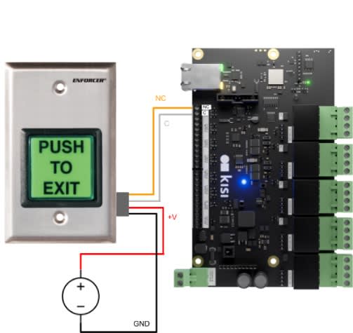
- Connect the COM output to one of the GND ports of the controller.
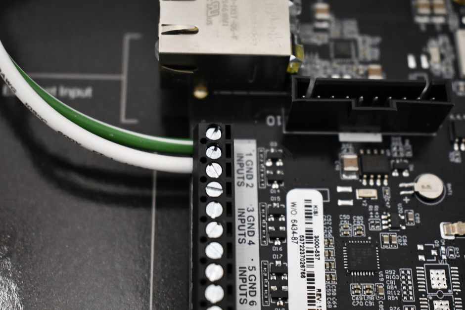
- Connect the NC output to one of the numbered General Input ports on the controller.
- Connect the + port to the positive terminal of a power source.
- Connect the - port to the negative or ground terminal of a power source.
- Some push to exit buttons are simpler and only have positive and negative wires. In this case, just connect positive to an input pin and negative to a GND pin.
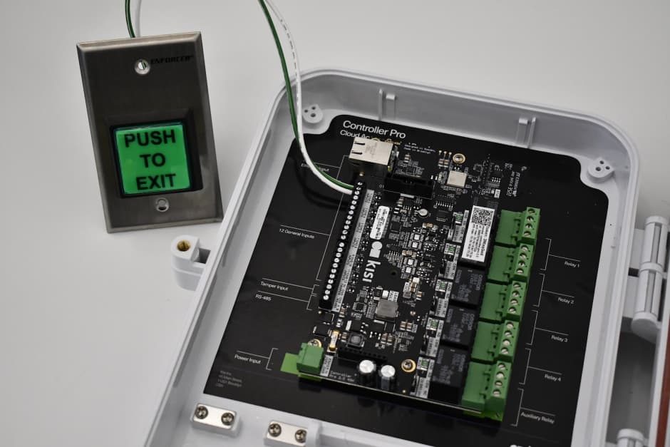
When finished, it should look similar to the images below. Note: No external power source was needed for this button.
No touch exit buttons, also known as touchless exit buttons, serve the same purpose as push to exit buttons. They are a request-to-exit device, enabling you to open a locked door to exit without needing credentials. A no touch exit device will sense if someone’s hand is within six inches (15 centimeters) and automatically unlock the door so they can exit.
Watch the video below for more information on no touch exit buttons, their benefits, use cases, and installation tips.
Like other REx devices, no touch exit buttons are suitable for any electronically locked door settings that need a free exit option. Combining the benefits of a push to exit button and a motion sensor, they are used in commercial, residential, and industrial settings.
No touch exits are more sanitary and ergonomic than a physical button, and provide a hygienic and convenient way to exit a space without physically touching a surface. These buttons are particularly relevant when minimizing the spread of germs and promoting hygiene is important, making them ideal in healthcare settings, public buildings, educational institutions, and other high-traffic settings.
Be sure to unplug your Kisi Controller Pro 2 before wiring. To add a no touch exit button to your Kisi access control system, you will need the following:
- Kisi Controller Pro 2
- No touch exit button
- External power source
- Small flathead screwdriver
Hardware setup
- Ensure the controller is unplugged.
- Identify the General Input pins on the left side of the Kisi Controller Pro 2.
- Wire according to the schematic below.
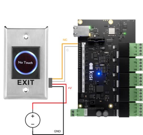
- Connect the COM output to one of the GND ports of the controller.
- Connect the NC output to one of the numbered General Input ports on the controller.
- Connect the + port to the positive terminal of a power source.
- Connect the - port to the negative or ground terminal of a power source.
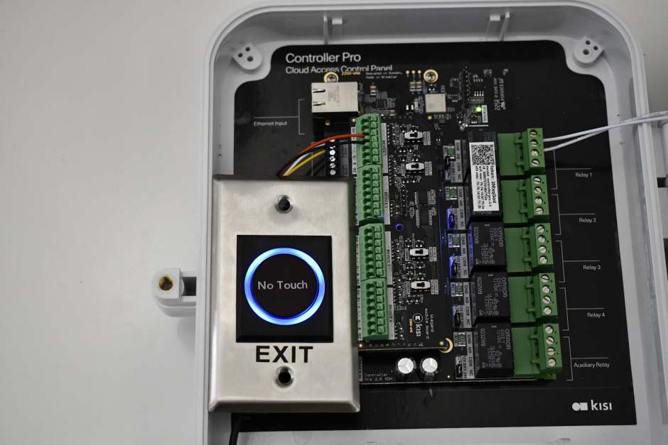
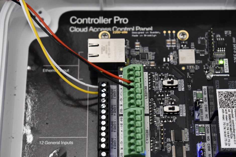
When finished, it should look similar to the images below. Note: In this example, we used the Kisi Wiegand Board as a power source for demonstration purposes. We do not recommend this as a permanent solution.
Door motion sensors #
Door motion sensors are devices designed to detect movement near or around doors. They offer a range of compelling benefits, including automation, hygiene, and accessibility, making them a valuable addition to any commercial space. With Kisi, you can use door motion sensors to automatically unlock doors when motion is detected. Door motion sensors can also be used as a security measure for one-way unlocking.
Watch the video below for more information on door motion sensors, their benefits, use cases, and installation tips.
Door motion sensor use cases #
Installing door motion sensors on automatic doors can make your spaces more accessible, enabling people with mobile disabilities to enter more easily. This hygienic door-unlocking method can prevent the spread of germs, as the motion sensor can automatically open a door with no need for contact with the surface.
Like the other types of REx devices, door motion sensors allow one-way free access to doors. Making it easy to leave from the inside automatically but still maintaining security from the outside by requiring a credential to enter.
Door motion sensors can also enhance user experience in commercial spaces assisting people carrying large items that would have trouble using a manual door. You can use sensors to track the number of people entering and exiting the space, providing valuable data for optimizing space utilization.
Guide to installing a door motion sensor #
Be sure to unplug your Kisi Controller Pro 2 before wiring. To add a door motion sensor to your Kisi access control system, you will need the following:
- Kisi Controller Pro
- Request-to-exit door motion sensor such as the Bosch DS150i
- External power source
- Small flathead screwdriver
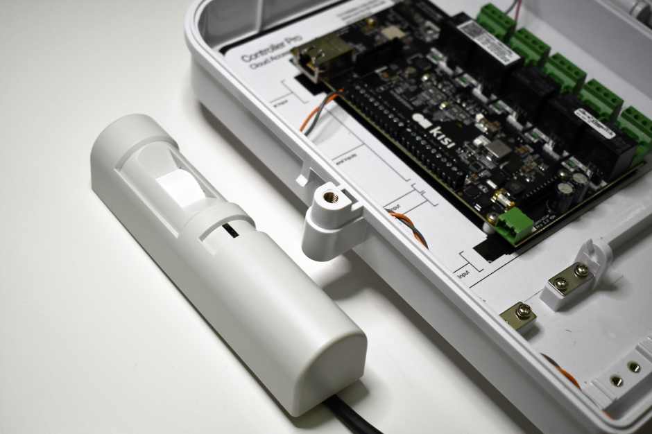
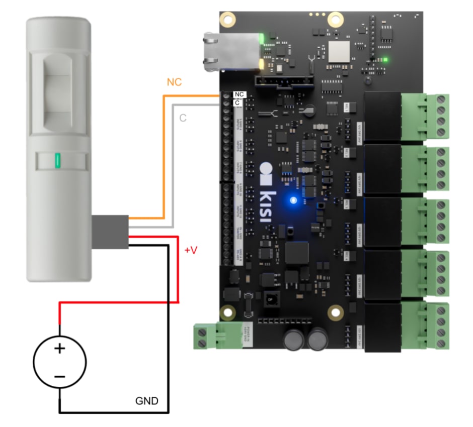
Hardware setup: Wiring the door motion sensor
- Unplug power from the Kisi Controller Pro prior to wiring for safety.
- Read the datasheet for the door motion sensor. Take note of which wire color corresponds to NC (Normally Closed), C (Common), +Voltage, and Ground.
- On the Kisi Controller Pro, identify the general inputs on the left side of the board. Note: Two IN (Input) pins share one GND (Ground): IN1, GND, IN2, GND, IN3, etc.
- Wire the C (Common) wire of the door motion sensor to the GND pin of the controller.
- Wire the NC (Normally Closed) wire of the door motion sensor to the IN pin of the controller.
- Wire the +V and GND of the door motion sensor to an external power source. If you have a Wiegand board and have an unused channel, you can use the + and - pins as a power source (12 volts direct current and maximum 375 milliamperes).
- Verify that all connections are secure and there are no loose wires before repowering.
Request to Exit software setup #
Follow the steps below to connect your Request to Exit. These step-by-step instructions are suitable for connecting both your push to exit and no touch buttons to the Kisi access control system.
- Sign in to ‘Kisi’.
- Navigate to ‘Places’ and select the place you want to configure the request-to-exit device for.
- Navigate to ‘Hardware’ in the left-hand menu and select ‘Controllers’.
- Select the controller that has the request-to-exit device wired to it.
- Scroll down and click on ‘Inputs’.
- Select the input that the request-to-exit is wired to.
- Under ‘Type’, select ‘Request to Exit’.
- Under ‘Door’, select the door the request-to-exit device is wired to.
- Under ‘Duration’, define how long the relay should be triggered.
- Under ‘Action on Access’, select ‘Unlock door’. When triggered, the request-to-exit button will unlock the door.
- Under the ‘End of Line Type’ section, specify the desired end-of-line status that you want Kisi to detect. Cut detect: Detects if the wiring is cut. Short detect: Detects if the wiring is shorted. Cut and short detect: Detects both cut and shorted wiring scenarios.
- Enable the toggle.
- Click ‘Save’.
Tip: You can disable your request-to-exit devices anytime using the same Hardware tab.
Where to get power from?
You may have a few options for a power source during your installation. The main options we will discuss are external power supply and the Kisi Controller’s power outputs.
We recommend powering your ancillary components based on an external power supply. An external power supply is more likely to provide the amperage you need to power those components. As a reminder, if you pull more than 4A through the Kisi Controller, the board will short-circuit and become useless.
If you are in a situation where you do not have a power supply on hand and need to power a small amount of ancillary components, you can elect to use the power outputs located on the Kisi Controller.
How to connect the REX button with the rest of the circuit?
The typical REX button has 5 wires (+, -, COM, NO, NC), although only 4 are needed for normal operation. Two wires (+, -) will power the LED on the button, and two wires ( C-NC or C-NO) will serve as signal wires that connect to the rest of your installation components (lock, Kisi, other ancillary parts).
Note: + and - can sometimes be labeled as LED+ and LED- but are essentially the same.
If you are not completely familiar with installing REX buttons, Kisi highly recommends that you make your connections one pair at a time. The easiest connection order is as follows:
- Connect and power the LED on your REX button
Connect + and - on the REX button to power the LED light using a 12/24V power supply. When you plug the power supply in, you should see the LED light of the button turn on. If the button does not light up, you may have to observe the polarity of the LED. Swap the wires on the button’s terminals and plug in the button again to test.
- Connect the circuit signal wires to Common (COM) and Normally Closed (NC)
If you are wiring a Fail-Safe lock, you must maintain a closed (Series) circuit to continuously power your lock. From the COM port on the REX, connect to the positive lead of your power supply. From the NC port on your REX, connect to the COM of the next hardware component in the circuit. This could be a motion sensor, maglock, or Kisi.
In order to test this connection, you will need to wire the button to power.
- Connect and power the REX button itself (separate from the LED in step 1)
This connection will provide power to your REX button. Connect the negative terminal from your REX button to the negative lead from your power supply. Then, connect the positive terminal from your REX button to the positive lead from your power supply.
When you plug your power supply back in, you should have the LED of the button turned on. As long as you’ve completed the rest of your circuit, when you press the button, it should open your circuit and release the door lock.
What if the button does not release the door?
A failure in the controlling circuit is preventing power from being interrupted to the lock. It could be a shorted wire in a power transfer, or some other failed device in the circuit.
To identify the issue, you should test each option to open the circuit. In most cases that will be the keypad, push to exit button, motion sensor, and Kisi. If you can open the circuit with other components, then you can narrow down your issue.
Assuming the issue exists with the REX button, you should double check all of your connections. Make sure you observe polarity in your power connections and make sure your signal wires are connected to the proper terminals (NC and COM). If the issue still persists, the REX button may be damaged and you should consider installing a new button.
How to choose the right push to exit button for your access control system?
The right exit button for your access control application will depend on your existing door-locking system. The available exit buttons include:
- N/C circuits – Normally Closed Circuit
- N/O circuits – Normally Open Circuit
- COM option
The N/C interrupts power flow when the exit button is pressed, while the N/O allows power to flow when the button is pressed. The COM option can operate for both closed and open circuits. Ensure that you use the right push to exit button, which is compatible with your access control system.


